k24 test engine - part 5
Project K24 Part 5
Welcome back to our K24 engine project, where we are attempting to achieve the most power possible by carrying out modifications above the head gasket only and leaving the bottom end of the engine stock.
At the end of the previous episode we had swapped the RBB cylinder head found on the stock K24 for the PRB head found on the K20A2 and optimised the inlet manifold plenum volume.
To make the most of the additional airflow from the PRB head more camshaft lift (and possibly duration) is required due to the fact that the PRB flows more air at larger valve openings (see flow chart below).
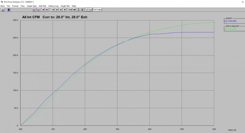
Two more cam profiles were tried and the best of the two were used moving forward. You can see the result from adding more camshaft lift below:
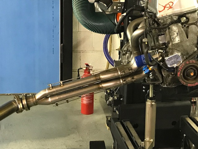
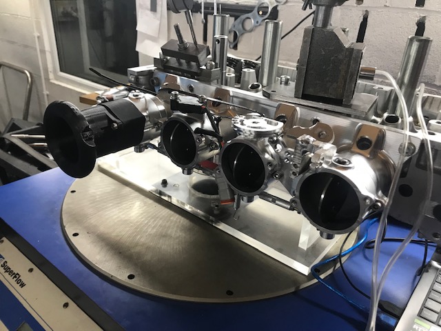
The next area for attention is the header, we have fabricated an adjustable exhaust manifold for development purposes and optimization on our engine dyno. This allows us to achieve the best possible power for any given setup rather than being stuck with ‘off the shelf headers’. Our header allows adjustment of primary lengths, secondary lengths as well as cylinder pairings, the header can also be used in 4-2-1 and 4-1 configurations.
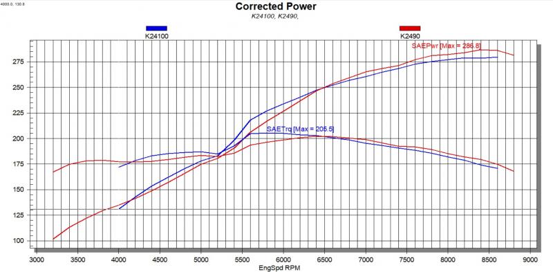
Over the next 45 dyno runs primary lengths, secondary lengths and cylinder pairings were adjusted until the best spread of power was found, the result can be seen below:
At this point we are sure that no more power will be gained without increasing the airflow through the cylinder head, we can verify this in two ways. Firstly a simple approximation calculation (see below)
HP = .25714 x cfm x no. of cylinders therefore .25714 x 294 (from airflow graph above) x 4 = 302hp
So a rough approximation of the max hp available using the calculation is 302hp (note that this calculation assumes that the compression is optimum (which it most certainly is not!)
The second method that we use to verify that the head flow is at maximum is carried out on the flowbench and then the dyno. First of all we flow test the head with the inlet valves at the max lift of the camshaft profile used, we then add an inlet (in this case a set of our ITB’s) and retest, if the inlet offers no restriction and the power does not increase when the inlet is fitted to the engine then this concludes an airflow restriction in the head.
The dyno graph below shows the previous best dyno run (in blue) vs a dyno run with the ITB’s added.
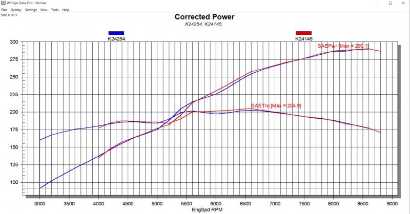
As you can see, this confirms that no more power can be made without increasing the airflow through the cylinder head.
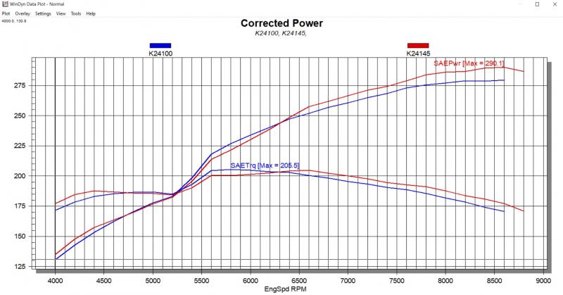
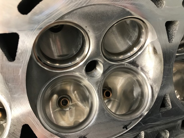
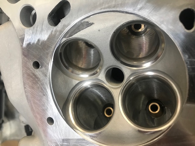
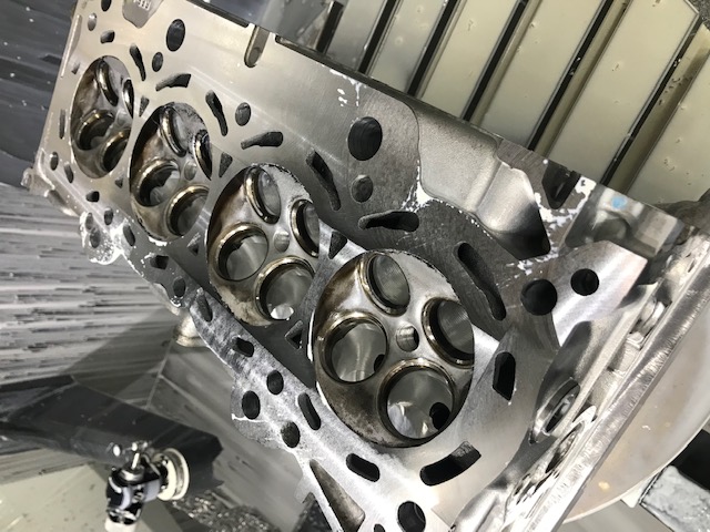
To achieve the greater airflow required we are going to switch out the stock PRB cylinder head with one of our CNC ported RBB cylinder heads. The head has had our race guides fitted, 5 axis CNC porting to both inlet and exhaust as well as our proprietary seat profiles also to both inlet and exhaust.

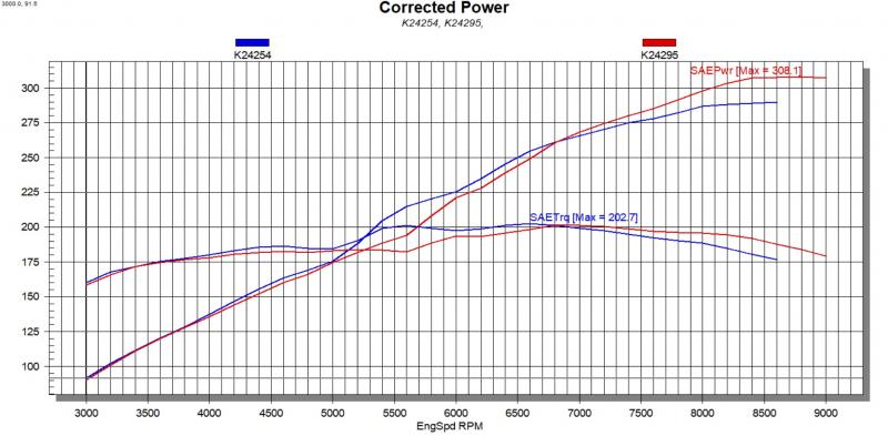
If we had not shown that the head flow was holding the power back previously, we have certainly confirmed it now (see dyno graph below) that’s an 18hp increase!
Note.
Not too much attention has been paid to optimizing the VTEC crossover point, this may account for what appears to be a midrange loss of power.
At this point we would like to give some information on how we and others measure hp and torque. All engine dyno’s measure torque at the flywheel and correct this to a ‘standard’ ie SAE or DIN for example. CPL Racing use SAE. We have noticed that most U.S. based Honda tuning companies use ‘STP’ correction (below are 3 examples of this)
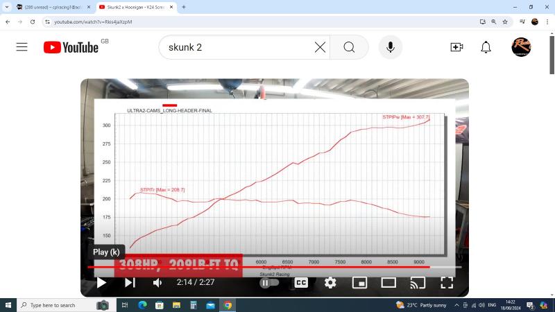
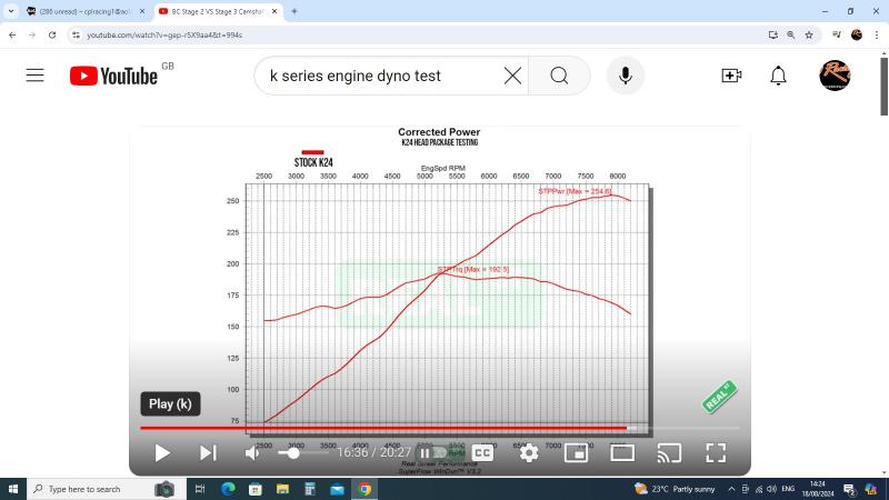
From what I can see ‘STP’ power is something for the marketing departments that feel that SAE/DIN don’t read high enough for them to sell products/services.
Below is a dyno graph showing what our final result would be using ‘STP’ correction
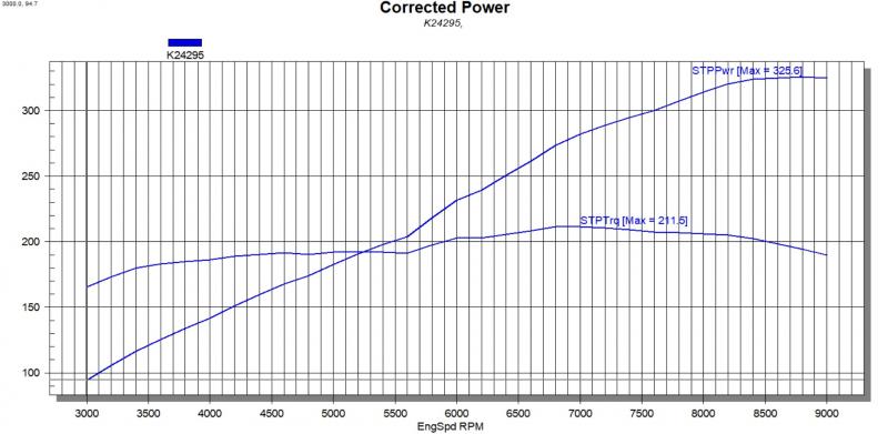
It’s up to you which power output that you consider correct, however all of the comparisons made in this project have been carried out using ‘SAE’ correction and testing as noted on each graph.
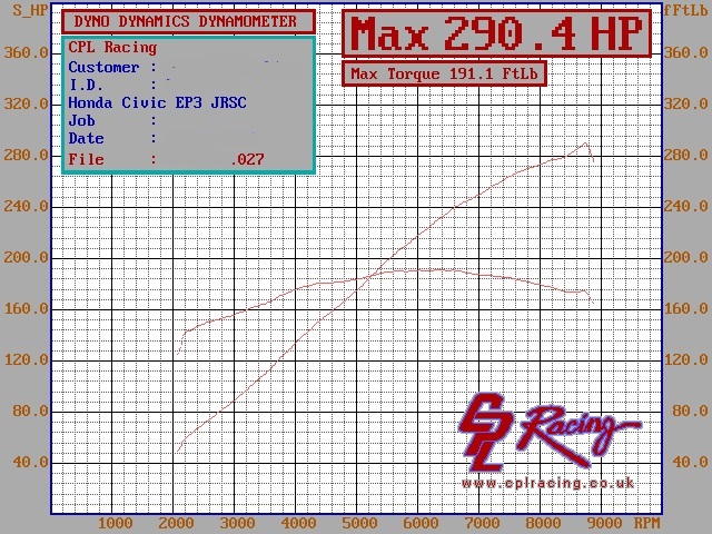
One last closing thought on what has been achieved with this ‘Stock bottom end’ K24 long block. Below is a graph showing a supercharged K20, a conversion that we have carried out literally hundreds of in the past (more than 300). These conversions typically made anywhere between 280 and 300hp so the below graph is a typical example
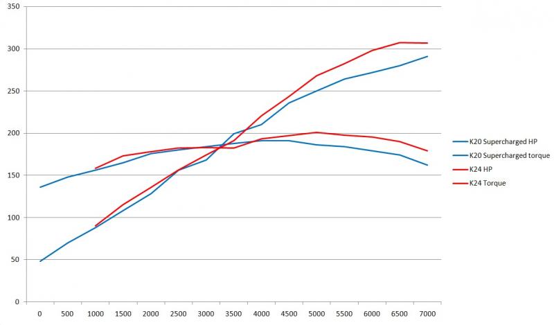
Whilst we knew that we could achieve far better performance from a complete long block K24, our ‘unwritten’ goal was to see if we could out perform a supercharged K20 without touching the K24 bottom end. Below you can see both the K24 and Supercharged K20 overlaid for comparison. Interesting to see that the K24 outperforms the supercharged K20 even at the lower end of the rev range where a supercharger is meant to excel.
There you have it, we hope this gives you an insight on just how great a well tuned K24 can be even with the limitations of the stock bottom end.
This long block is now available for sale, if this is something that you are interested in please email cplracing1@aol.com with any questions.
.


Terms and Conditions of Trade
Privacy Policy
Returns Policy
© 2025. CPL Racing
CPL Racing is a trading name of Chamberlain Precision Limited
Registration number 4219332
Site By 321-Designs